- PHONE :0086-15621008853
- EMAIL : admin@qdyili.com
Steel Structure System
You Have a Vision. We Can Help. Receive a Free Quote and Drawing Within 24 Hours.
Steel Structure System
A steel structure system is a metal structure that is made of structural steel components that connect with each other to carry loads and provide full rigidity. The steel structure system is a structure mainly made of steel. The characteristics of steel are high strength, lightweight, excellent overall rigidity, and strong deformability. So it is especially suitable for large-span, super-high and super-heavy buildings.

The steel structure system shows the specification of the portal frame structure, bracing system, interior structure system, painting system, commercial mezzanine system, transport system (conveyors, lifts, etc), glass structure system, floor system which most common use building structure for Warehouse, Workshop, Garage, Aircraft Hangar, and riding arena.
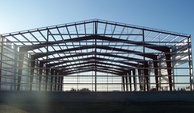
steel structure system-Portal frame structure
Portal frames are now commonly used to create wide-span enclosures such as; warehouses, agricultural buildings, hangars, workshops, factories, riding arena, and so on, where a clear space is required uninterrupted by intermediary columns. They were originally used because of their structural efficiency, meaning that large spaces could be enclosed with little use of materials and for a low cost.

The portal frame can divide into single-span (Figure a), double-span (Figure b), multi-span (Figure c) cantilever steel frame (Figure d) ) and steel frame with the adjacent frame (Figure e).
In the multi-span rigid frame, the connection between the column and the roof beam generally hinged, and the multi-span rigid frame single-slope roof (Figure f).
The multi-span rigid frame consisting of multiple double-slope roofs can also be used (Figure g). The beam-column cross-section can be equal or variable, and the base of columns hinged or rigid connected.

The table presents some general guidelines for the design of portal frame structures. The minimum roof slope, allowing for deflections, is normally taken as 16%. The columns are often heavier than the rafters and the column height is approximately one-fifth of the frame span. The spacing of the frames depends on the spanning capabilities of the purlins and the snow loading.
|
Guidelines for portal frame design |
|
|
Parameter |
Typical value |
| Span of portal frame | 15 to 40m |
| Spacing of frames | 5 to 8m |
| Roof slope | 16% |
| Rafter depth | Span/50 to Span/60 |
| Ratio of span to column height | 4 to 7 |
| Column weight (kg/m) | 1.5 to 2 × Rafter weight (kg/m) |
| Spacing of purlins | 1.5 to 2m+ |
Notes:
- No cranes or heavy additional loads
- Purlin spacing reduced close to the haunch to provide stability to the haunch
Length and Width :
Generally speaking, according to the principle that the long side is greater than the width, the amount of steel used in the rigid frame can be reduced, and the support between the columns can be reduced, thereby reducing the amount of metal used in the support system.
Example 1: The size of the building is 60x50m, 60m should use as the length and 50m as the width, that is: 60 (L) x50 (W), not 50 (L) x60 (W).

Column Distance:
The most economical column distance under standard load is 7.5-9m. When it exceeds 9m, the steel consumption of roof purlin and wall girt will increase too much, and the overall cost is not economical. The standard load here refers to 0.3KN / m2 for live roof load and 0.5KN / m2 for essential wind pressure. When the loading is more significant, the economic column distance should reduce accordingly. As or a workshop building with more than 10 tons crane, the financial column spacing should be 6-7m.
When arranging column spacing, if unequal column spacing is required, try to arrange the end span column spacing to be smaller than the center span. It is because the wind load at the end span is larger than the center span. Besides, when using continuous purlin design, The deflection of the end span and the mid-span bend are always more significant than other spans. Using smaller end spans can make roof purlin design more convenient and economical.
Example 1: Building length = 70m
Economical column distance is available: 1 @ 7 + 7 @ 8 + 1 @ 7 or 1 @ 8 + 6 @ 9 + 1 @ 8
Example 2: Building length = 130m, with a 10-ton crane
Economical column distance is preferable: 1 @ 5.5 + 17 @ 7 + 1 @ 5.5 or 20 @ 6.5
Determination of a reasonable span
Different production processes and use functions largely determine the span of the metal building. Some owners even require steel building manufacturers to determine a more economical span based on their useful features. A reasonable span should decide according to the height of the steel building. In general, when the column height and load are constant, the span is appropriately increased. The increase in steel consumption of the rigid frame is not apparent, but it saves space, the foundation cost is low, and the comprehensive benefits are considerable.

Through a large number of calculations, it finds that when the eaves height is 6m, the column distance is 7.5m, and the load conditions are entirely consistent, the steel consumption of the rigid frame (For Q345B steel) width between 18-30m is 10-15kg / m2. The amount of metal used for rigid frame units between 21-48m is 12-24kg / m2. When the eave height is 12m, and the width exceeds 48m, a multi-span rigid frame (sway column set in the middle) should use. The frame saves more than 40%, so when designing the rigid portal structure, you should choose a more economical span according to specific requirements, and you should not pursue a large span.
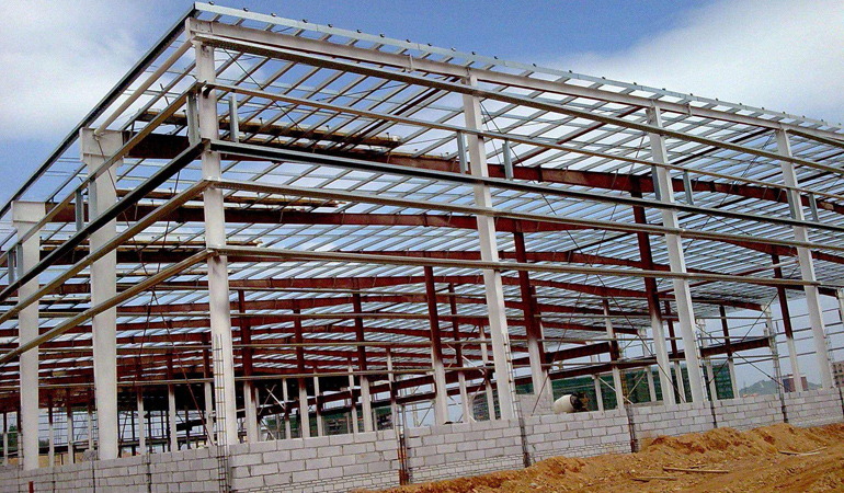
steel structure system-steel Components
Portal steel frame often uses welded or hot rolled H-section steel as the main load-bearing framework, and cold-formed thin-wall steel (C/Z section steel or channel steel) as purlins and wall girt. It is a lightweight building structure that uses a corrugated single color sheet as the roof, wall panel. Rock wool and glass wool as thermal insulation materials, and round steel or angle steel as the roof and wall bracing.
Main materials:
- Q235, Q345 H section steel structure for columns and beam
- Pre-embedding anchor bolts for connection columns to foundation
- Intensive bolts for connection tween columns and beams
- Wall/roof panel: one layer corrugated steel plate or sandwich panels
- Windows/doors, PVC, aluminum alloy, steel, etc.
- Color steel plate or galvanized steel gutters and PVC tubes for rain water
Surface:
There are two main surface treatment methods for steel structure components:
Hot dip galvanized
YILI Steel Structure own the hot dip galvanize zinc pool ourselves, pool size: 10.5x1.8x2.4m (LXWXD). The molten metal in the working area of the galvanizing bath shall contain not less than 98% by mass of zinc. The bath may contain certain deliberately added elements to achieve special properties.
painted
Our painting process including alkyd paiting, two primary painting, two finish painting (gray paint, red paint, white paint, epoxy zinc etc.)
steel structure bracing system
A bracing system is a secondary but essential part of a steel structure system. A bracing system serves to stabilize the main girders during construction, to contribute to the distribution of load effects and to provide restraint to compression flanges or chords where they would otherwise be free to buckle laterally.

There are two major bracing systems:
- Vertical bracing system
- Horizontal bracing system
Vertical Bracing System for Steel Structures
Vertical bracing as shown in Figure-2 is diagonal bracings installed between two lines of columns. Not only does it transfer horizontal loads to the foundations (create load path for horizontal forces) but also it withstands the overall sway of the structure.

Vertical Diagonal Bracing Provided Between Two Lines of Columns
Configurations of vertical bracings include cross diagonals (cross bracing) and single diagonal. In the former case, bracings are slender and withstand tension forces only, so they will not resist compression forces. Therefore, tensile diagonals provide necessary lateral stability in addition to the floor beams that act as a part of bracing system. Figure-2 shows the placement of cross bracings between two lines of columns.

Single Bracing Provides Resistance Against Compression and Tension
As far as the single diagonal bracing is concerned, it is designed to resist both tension forces and compression forces. The arrangement of diagonal bracing is illustrated in Figure-3. Bracing elements are commonly placed at nearly 45o because it not only offers an efficient system compare with other systems but also strong and compact connections between bracing member and beam-column juncture will be achieved. It is worth mentioning that, if the bracing member inclination is smaller than 45o (angle from vertical), then the sway sensitivity of the structure would be increased whereas wider bracing member arrangement provide greater structural stability.
Vertical bracing systems are required to be designed to resist wind forces, equivalent horizontal forces that represent the influence of initial imperfections and second order effects caused by frame sway in the case of the flexible frame.
Horizontal Bracing System for Multi-Storey Steel Structures
Horizontal bracing systems purpose is the transfer of horizontal loads from columns at the perimeter of the structure to the planes of vertical bracing. The horizontal forces on perimeter columns are generated because of wind force pressure on the cladding of the structure. There are two major types of horizontal bracing systems which are used in the multistory braced steel structure namely: diaphragms and discrete triangulated bracing. Regarding diaphragms, there are various types of floor systems that some of them provide perfect horizontal diaphragm such as composite floors whereas others such as precast concrete slabs need specific measures to satisfactory serve their purpose. For example, steel work and precast concrete slab should be joint together properly to avoid relative movements. As far as discrete triangulated bracing is concerned, this type of bracing is considered when floor system cannot be used as a horizontal bracing system. It is a horizontal system of triangulated steel bracing placed in each orthogonal direction. The horizontal bracing are placed between supports which commonly are locations of vertical bracings Regarding bracing at roof level, wind girder is used to resist horizontal forces at the top of the columns.

Horizontal Bracing Placement
Advantages of steel structure system
The steel is toughness, good plasticity, uniform material.
Steel is high structural reliability, suitable for bearing impact and dynamic loads, and excellent seismic performance.
The internal structure of the steel is uniform, close to an isotropic homogeneous body. The actual working performance of the steel structure is more in line with the calculation theory. Therefore, the steel structure has high reliability. Compared with concrete and wood, the ratio of density to yield strength is relatively low. Thus, under the same stress conditions, the steel structure has a small section, lightweight, convenient transportation, and installation, and is suitable for large spans, high heights.
The steel structure is heat-resistant and not fire-resistant.
When the temperature is below 150°C, the properties of the steel change little. Therefore, the steel structure is suitable for hot workshops, but when the surface of the structure is exposed to the heat of about 150°C, it should protect by heat insulation panels.
When the temperature is between 300℃ and 400℃, the strength and elastic modulus of the steel will decrease significantly, and the strength of the steel will tend to zero when the temperature is around 600℃. In buildings with special fire protection requirements, the steel structure must be protected by refractory materials to improve the fire resistance level.

The steel structure has weak corrosion resistance.
Especially in the environment of the humid and corrosive medium, it is easy to rust. Generally, steel structures must be de-rusted, galvanized, or painted, and regularly maintained. For offshore platform structures in seawater, special measures such as “zinc block anode protection” are required to prevent corrosion.
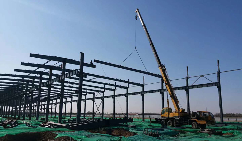
The high degree of mechanization of steel structure manufacturing and installation.
Steel structural components are natural to manufacture in factories and assembled on site. The factory mechanized manufacturing of steel structural components has high precision, high production efficiency, fast site assembly, and a short construction period. The steel structure is the most industrialized.
High strength and seismic resistance
Compared with ordinary reinforced concrete structures, steel structures are superior in inhomogeneity, high strength, fast construction, good seismic resistance, and high recycling rate. Steel has many times higher strength and modulus of elasticity than masonry and concrete, so the mass of steel members is light under the same load conditions. From the aspect of being destroyed, the steel structure is a flexible damage structure with large deformation foreshadowed in advance, which can detect the danger in advance and thus avoid it.
